
TRANsmission (Robot w/ Synchronous Transmission)
At MIT, I took a Design and Manufacturing, where the instructors create a course for students to individually design and compete with robots made from scratch. In the spring of 2019, the theme was Moonshot where the playing field was modeled after the moon. To score points, students could pick up rocks, place a flag at different heights, pull down fuel rods, spin APS chargers, pull up antennas, or climb back up the ramps to the lunar module.

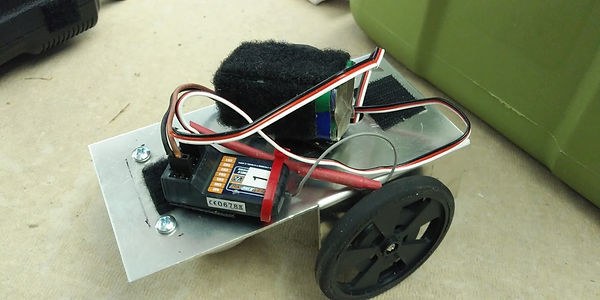
When the class began, each student built a "mini-me" which was a simple, foundational robot.
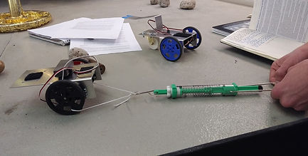

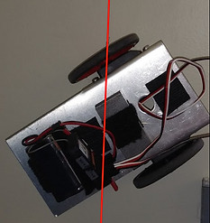

With our mini-me's, we ran tests to practice measuring conditions like the center of mass of our robots, the coefficient of friction, velocity, torque, and slip/tip conditions.
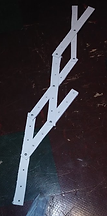
As the class continued, my strategy was to place a flag and collect rocks. I created some quick prototypes for linkages out of foam-core to test different geometries for different lifts. Rearranging the foam-core bars, I created scissor lifts, 4-bar, and 6-bar lifts.


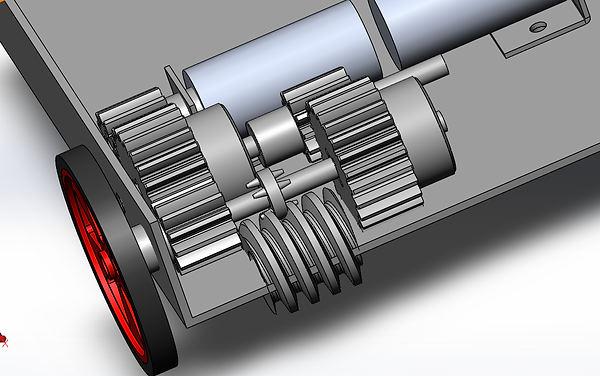
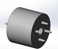
Looking at past robots, I was inspired to create a variable transmission for my robot to optimize its speed for different tasks. I took inspiration from a manual car transmission, utilizing a dog clutch to engage and disengage my gears. Thus, the motor will be constantly driving a set of gears, but power is only transmitted to the wheels when the dog clutch engages with either of the gears. I created a rough CAD assembly of a variable transmission system with gear CADs from McMaster.
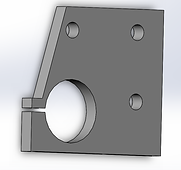
After talking to my instructors and doing more research, I returned to my CAD, and installed new parts, like supports, sliders, and a longer dog clutch.
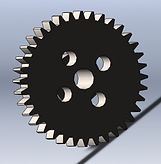
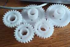
Then, after seeing what gears were available, I arranged the gears to make the geometry easier wherein one mode, the gearing is 1:1, while in the other mode, the gearing is 2.25:1.
Next, after seeing a slider prototype designed by one of the shop instructors, I made a slider that moved by turning a threaded rod. Therefore, both sliders on either side could be kinematically linked if turning on the same rod. This would allow for both clutches on either side to engage the correct gear at the same time, so there will not be stalling when changing gears.


To verify the feasibility of the transmission, I ran some rough calculations. After estimating the weight of my robot combined with the weight of the rocks, I got a torque that the motors would need to climb the ramp and drive along the flat ground. I also imposed time constraints to deduce a speed that my robot should drive at to maximize the points I could get from collecting rocks.
From there, I ran calculations to check the LDO motors' performance and compare them to my torque and speed criteria, when using 4 of the same motors at their optimum power output. While the 57:1 LDO motor got close, none of the motors fully satisfied both criteria.
I ran the same analysis for my transmission assuming a 15% frictional loss at each gear interface. While the transmission also wasn't able to satisfy all the criteria, it did satisfy slightly more than no transmission, being able to climb the ramp (in 2.25:1 gear mode), but having a lower torque output while on the floor (in 1:1 gear mode).


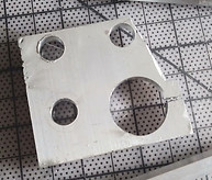

After manufacturing my parts, I realized I needed to make adjustments to increase the tolerance so all the parts fit together. For example, some holes were enlarged to allow the axle to fit through all the holes. The more I sacrificed on tolerance, the less rigidly the pieces fit together, creating slack between some of the axles and gears, which caused a lot of rattling and power loss in the transmission system.

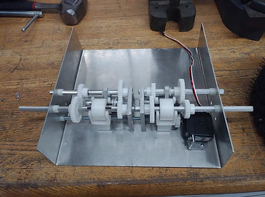
After spending hours remanufacturing parts, I learned that by making a more rigid assembly, the misalignments in the axle can increase the frictional loss significantly. To solve for the misalignments, I added spacers to the supports and properly leveled the axles, while ensuring their contact with the gears. After hours of adjusting, the transmission was finally running smoothly.
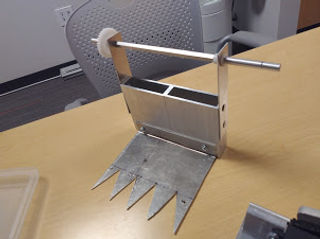
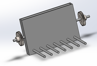
Next, I started on the manipulator that I wanted to use to collect rocks. I created a dumper that would load rocks onto the robot. By giving the dumping mechanism 2 degrees of freedom, one to lift the dumper and another to pivot the dumper, it gave my robot more flexibility at dumping rocks, and potentially placing a flag.
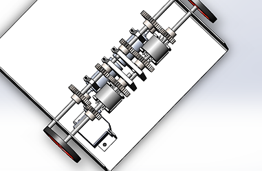
I also decided to give my robot all-wheel drive, rather than simply having the two back wheels driving to reduce the likelihood of my robot slipping as it went up the ramp. By using a belt, I connected the front and back wheels to drive together. While this did sacrifice some of my robot's maneuverability, I thought the added ability to make it up the ramp was more important.


With the final weeks in the class drawing near and the competition right around the corner, I rushed to finish my robot. I added walls to create a bay where rocks could be held on my robot. Then, I identified all the strengths and weaknesses in my design to prioritize which problems to fix.

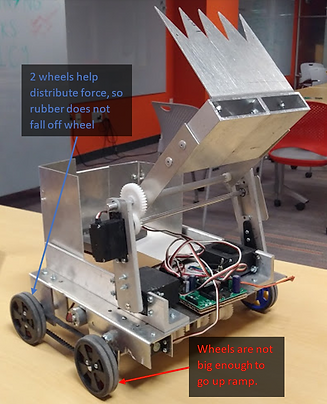


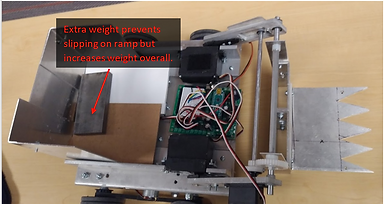

With everything designed, I ran some test runs to see how my robot fared in the competition. The biggest issue that I didn't identify until the end of the term was that my chassis and transmission system was too close to the ground, and too wide, so with the wheels I had, there was no way it could make it up the ramp.
I tried manufacturing bigger wheels, but because the big wheels raised the center of mass of the robot, it caused the robot to flip every time it hit the ramp.
By the end, I realized the main feature of this robot was the synchronous transmission system for driving, and while it might not have helped me much with the overall competition, I was proud that I overcame the challenge. Thus, I decided to strip my robot bare with nothing but a simple flag placer that could be used to place a flag at the bottom of the ramp. While I didn't score much at the competition, my transmission worked perfectly.

